


Power Distribution Module (PDM)
Installation & Setup Guide
Version: 1.03
Date: 03.23.2026
Important Compatibility Notice
The Aces EFI Power Distribution Module is intended for Aces EFI Gen 2 systems by default. Gen 2 systems are designed to use the PDM as the primary switched power-distribution device for the EFI system and related components.
Gen 1 systems are different. Gen 1 systems have relays wired into the main harness, while Gen 2 systems do not. Because of that, Gen 1 systems, or any system with relays already integrated into the harness, require a different wiring approach.
Do not wire a Gen 1 or relay-integrated harness exactly like a standard Gen 2 PDM installation unless the original relay architecture has been intentionally removed or redesigned.
If you are installing the PDM on a Gen 1 system, review the Gen 1/Relay-Integrated Harnesses section before making any connections.
1. Product Overview
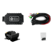
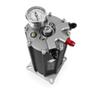
The Aces EFI Power Distribution Module is a compact power-management solution designed to simplify wiring and centralize switched power distribution for EFI systems and related accessories.
The PDM distributes 12 V battery power across multiple controlled output channels and is designed to support key EFI-related circuits, such as:
- ECU main power
- Fuel pump power
- Cooling fan control
- Relay-fed accessory circuits
- Ignition-switched outputs
- Tachometer signal routing
By centralizing these functions in one module, the PDM helps reduce wiring clutter, improve serviceability, and create a cleaner, more organized installation.
The PDM uses IGBT transistor-based switching in place of conventional electromechanical relays, helping filter harmful transient voltage and provide improved protection for connected electronics.
2. Key Features
The Aces EFI PDM is designed to provide:
- Centralized power distribution for Aces EFI installations
- Independent switched control of major system circuits
- Fused output protection
- Clean ignition-switched outputs
- Simplified wiring with clearly identified terminals
- Support for fuel pump, fan, ECU main power, and relay-fed accessory circuits
- Compact mounting for easier installation in a wide range of vehicles
3. Supported Functions
The PDM is designed to manage and distribute power for the following common system functions:
- Main ECU power
- Fuel pump power
- Fan control
- Auxiliary relay-fed accessories
- Ignition-switched outputs
- Tachometer / POINT signal routing
The PDM is not intended to be used as an unrestricted universal power box. Every output channel has a defined current limit and must be used within its rated capacity.
4. Terminal Identification
Use the terminal names below when wiring the PDM.
Power Interface
| Terminal | Function |
|---|---|
| VBAT | Main battery power input |
| GND | Main power ground |
Control Inputs
| Terminal | Function |
|---|---|
| VBAT | Main battery power input |
| GND | Main power ground |
| MRD | Main power control |
| RPUMP | Fuel pump control |
| RLY1 | Relay 1 control (Fan 1) |
| RLY2 | Relay 2 control (Fan 2) |
| RFAN | Fan control (AC fan) |
| IGNKEY | Ignition key signal control |
| POINT | Tachometer signal |
Output Channels
| Terminal | Function |
|---|---|
| VMAIN1 | Main power output |
| VMAIN2 | Main power output |
| VMAIN3 | Main power output |
| VPUMP | Fuel pump power output |
| VRLY1 | Relay power output |
| VRLY2 | Relay power output |
| VFAN | Fan power output |
| IGNSW1 | Ignition-switched output 1 |
| IGNSW2 | Ignition-switched output 2 |
| IGNSW3 | Ignition-switched output 3 |
| POINT | Tachometer signal routing |
Older Harness Revision Terminology
Some older wiring references may use alternate labels such as BAT+, BAT-, PUMP+, or IGNSW. In this manual, use the official PDM terminology above.
As a general reference:
- BAT+ corresponds to VBAT
- BAT- corresponds to GND
- PUMP+ corresponds to VPUMP
- Ignition switch input corresponds to IGNKEY
- IGNSW1, IGNSW2, and IGNSW3 are the switched outputs activated by IGNKEY
5. Specifications
Electrical Specifications
| Parameter | Specification |
|---|---|
| System type | 12 V vehicle system |
| Input voltage range | 9 to 16 V |
| Maximum input current | 60 A |
| Absolute maximum input voltage | 22 V |
| Output on-state voltage drop | 0.5 V or less at 10 A load |
| Switch response time | Less than 1 ms |
| Output efficiency | Greater than 96% at 10 A load |
Environmental Specifications
| Parameter | Specification |
|---|---|
| Operating temperature | -20°C to 105°C |
| Storage temperature | -20°C to 125°C |
6. Output Ratings and Fuse Assignments
Use the chart below when assigning loads to the PDM.
| Output Channel | Max Continuous Current | Fuse |
|---|---|---|
| VMAIN1 | 15 A | F4 |
| VMAIN2 | 15 A | F3 |
| VMAIN3 | 15 A | F3 |
| VPUMP | 15 A | F2 |
| VRLY1 | 10 A | F1 |
| VRLY2 | 10 A | F1 |
| VFAN | 10 A | F1 |
| IGNSW1 | 1 A | Built-in self-resetting protection |
| IGNSW2 | 1 A | Built-in self-resetting protection |
| IGNSW3 | 1 A | Built-in self-resetting protection |
Important Current Rules
- Each output channel must remain within its individual rated current limit.
- Channels that share a fuse must also remain within that fuse’s total combined capacity.
- Do not assume that because multiple outputs exist, they can all be loaded to their maximum value at the same time without checking shared fuse limits.
7. Control Logic
The PDM is an electronically switched module. Outputs are turned on by applying the correct signal to the corresponding control input. This means the PDM must receive the correct input signal before the related output will energize.
| Control Input | Controlled Output | ON Condition | OFF Condition |
|---|---|---|---|
| MRD | VMAIN1 / VMAIN2 / VMAIN3 | High level, recommended VBAT-3 V to VBAT | Low level, recommended 0 V to VBAT-5 V |
| RPUMP | VPUMP | High level, recommended VBAT-3 V to VBAT | Low level, recommended 0 V to VBAT-5 V |
| RLY1 | VRLY1 | High level, recommended VBAT-3 V to VBAT | Low level, recommended 0 V to VBAT-5 V |
| RLY2 | VRLY2 | High level, recommended VBAT-3 V to VBAT | Low level, recommended 0 V to VBAT-5 V |
| RFAN | VFAN | High level, recommended VBAT-3 V to VBAT | Low level, recommended 0 V to VBAT-5 V |
| IGNKEY | IGNSW1 / IGNSW2 / IGNSW3 | High level, recommended 2.5 V to VBAT | Low level, recommended 0 V to 1.2 V |
8. Before You Begin
Before installing the PDM:
- Disconnect the battery.
- Review the full wiring plan before making connections.
- Confirm whether the vehicle is using a Gen 2 system, a Gen 1 system, or a harness with relays already integrated.
- Identify which loads will be powered directly by the PDM and which functions are only control signals.
- Confirm the actual current draw of the fuel pump, fans, and any accessories before assigning them to a PDM output.
Mount the PDM in a dry, protected location away from direct heat, sharp edges, water intrusion, and moving components.
Whenever possible, mount the PDM close to the battery and ECU to minimize wire length and simplify routing.
Recommended Tools and Supplies
- Multimeter
- Wire crimpers and strippers
- Screwdrivers
- Heat-shrink tubing
- Electrical tape
- Electrical connectors
- Automotive-grade wire
- Proper grounding hardware
- Loom or abrasion protection as needed
9. Standard Installation Procedure for Gen 2 Systems
This is the default installation method for Gen 2 systems.
Step 1: Mounting the PDM
- Mount the PDM securely using the mounting holes provided.
- Choose a location that is dry, protected, and easy to service.
- Keep the unit away from exhaust heat, water exposure, and moving components.
Step 2: Connect Main Battery Power and Ground
- Connect “VBAT” to the battery positive.
- Connect “GND” to battery negative or to a verified chassis ground of equal electrical quality.
Keep both the power feed and the ground path short, direct, and appropriately sized for expected current.
Step 3: Connect Ignition Key Input
- Connect a true ignition-on source to “IGNKEY”.
This source should remain active during engine cranking. Do not use an accessory-only circuit that drops out during starting.
When IGNKEY is active, the PDM energizes:
- IGNSW1
- IGNSW2
- IGNSW3
These outputs provide clean switched power for supporting circuits.
Warning: Do not run ignition coils off of the PDM, or it will damage the system
Step 4: Connect ECU Main Power
- Use “VMAIN1”, “VMAIN2”, and/or “VMAIN3” for the ECU main power path as required by the system design.
- Use “MRD” as the main power control input for the VMAIN outputs.
- Follow the system wiring plan to determine which VMAIN outputs are used by the ECU and related circuits.
Step 5: Connect Fuel Pump Circuit
Use “VPUMP” as the fuel pump power output.
Use “RPUMP” as the fuel pump control input.
Verify actual fuel pump current draw before final connection. The fuel pump circuit must remain within the 15 A maximum rating of VPUMP.
Step 6: Connect Fan Circuits
Use “RLY1” and “RLY2” as control inputs for relay-fed fan stages or related switched circuits as required by the application.
Use “VRLY1” and “VRLY2” as the corresponding relay-power outputs.
Each of these outputs is limited to 10 A maximum, and both share fuse F1.
If a fan motor or fan stage exceeds the available PDM channel capacity, use the PDM output to trigger an appropriately rated external relay rather than powering the fan motor directly from the PDM.
Step 7: Connect Auxiliary/AC Fan Circuit
Use “RFAN” as the control input for the auxiliary fan circuit.
Use “VFAN” as the corresponding fan power output.
VFAN is limited to 10 A maximum.
Step 8: Connect Relay-Fed Accessories
Use “VRLY1” and “VRLY2” for controlled relay-fed accessories where needed.
These outputs are suitable for devices such as auxiliary pumps, secondary fans, or other switched accessories when used within their rated limits.
Step 9: Connect Tachometer/POINT Circuit
Use “POINT” for tachometer signal routing.
Treat the POINT circuit as a signal path only. It is not a load-power output.
10. Gen 1/Relay-Integrated Harnesses
This section applies to Gen 1 systems and any installation where relay logic is already built into the harness.
Why the Procedure Is Different
Gen 2 systems are designed to use the PDM as the primary switched power-distribution device.
Gen 1 systems already have relays wired into the main harness. In those systems, some harness wires may already act as relay triggers or relay-fed outputs rather than direct load-power circuits.
Because of that, a Gen 1 harness cannot simply be wired the same way as a Gen 2 harness.
Primary Rule
Do not wire a Gen 1 or relay-integrated harness exactly like a standard Gen 2 PDM installation unless the original relay architecture has been intentionally removed or redesigned.
Recommended Method for Most Gen 1 Installations
In most Gen 1 applications, the safest approach is to let the existing harness relays continue handling the final load switching while the PDM is used upstream as a cleaner power-distribution and controlled-feed device.
That means the PDM can be used to:
- provide clean, fused battery-fed power
- provide keyed switched outputs
- provide controlled feeds to relay-trigger or relay-fed accessory circuits
It should not be used to duplicate a switched output path that already exists in the harness.
What to Avoid
- Do not tie a PDM switched output directly into a circuit that is already receiving switched power from an existing harness relay.
- Do not feed a PDM output into the output side of an existing relay unless the circuit has been intentionally designed that way.
- Do not assume that a pump, fan, or ignition-labeled wire in a Gen 1 harness is always a direct load-power wire. It may only be a relay trigger.
- Do not double-switch the same circuit through both the original relay architecture and the PDM.
When a Full Conversion Is Acceptable
If the harness is being intentionally reworked so the PDM becomes the primary switching device, the original relay-fed output paths must first be removed, isolated, or bypassed correctly.
Only then should the final loads be reassigned to PDM outputs, and only if every circuit remains within the official output and fuse limits in this manual.
11. External Relay Guidance
An external relay may still be required in some applications.
Examples include:
- when a load exceeds the current capacity of the assigned PDM output
- when a fan circuit requires more current than the PDM can provide directly
- when a Gen 1 or hybrid installation still depends on conventional relay logic
- when the vehicle cannot maintain a stable keyed 12 V source during cranking in a non-PDM or hybrid setup
Relay Trigger Basics
Some relay-based systems use a positive trigger, where 12 V is applied to activate the relay.
Others use a negative trigger, where the relay has constant 12 V available and the switching side provides ground to activate it.
In relay-based fan setups, Fan 1 or Fan 2 may function as a negative-trigger relay signal rather than a direct high-current power output. Keep that in mind when integrating the PDM into older or relay-based systems.
Standard Automotive Relay Reference
Typical relay terminal functions are:
- Pin 30: fused battery power input
- Pin 87: output to accessory
- Pin 85: relay coil control side
- Pin 86: relay coil control side
- Pin 87A: normally closed terminal, often unused in these applications
12. Wiring Best Practices
For the most reliable installation:
- Keep battery and ground connections short and direct.
- Route high-current wiring and signal wiring cleanly and separately where practical.
- Protect wiring from abrasion, heat, and vibration.
- Verify the actual current draw before assigning any device to a PDM output.
- Use external relays when load demand exceeds the PDM channel capacity.
- Keep all shared-fuse loads within their allowed combined current.
- Use sound grounding practices throughout the system.
13. Startup and Verification
After all wiring is complete:
- Verify all connections against the final wiring plan.
- Confirm proper fuse placement.
- Reconnect battery power.
- Turn the ignition key to ON and verify correct system activation.
- Confirm ECU power-up.
- Test fuel pump operation.
- Test fan activation through the EFI control strategy.
- Verify communication between the ECU and connected peripherals.
- Confirm tachometer response if the POINT circuit is used.
- Start the engine and verify normal operation of all connected systems.
Inspect the wiring during initial startup for heat, loose terminals, abnormal voltage drop, or unintended switching behavior.
14. Troubleshooting
| Issue | Checks |
|---|---|
| No Power to Module |
|
| Fuel Pump Not Operating |
|
| Fan Not Operating |
|
| Ignition-Switched Outputs Not Active |
|
| Tachometer Issues |
|
| Unpredictable Operation on Gen 1 or Hybrid Systems |
|
15. Maintenance
Periodically inspect all electrical connections for:
- Corrosion
- Looseness
- heat damage
- Abrasion
- damaged insulation
Replace fuses only with the correct specified values.
Recheck grounds and high-current connections as part of routine service.
16. Safety and Operating Limits
Observe the following precautions at all times:
- Do not reverse the positive and negative power input connections.
- Do not exceed the rated current of any output channel.
- Do not exceed the total current limit of channels sharing the same fuse.
- Do not hot-plug the power supply while the load is operating.
- Do not expose the module to input voltage above 22 V.
- Remember that short-circuit protection is provided by the fuses. The module does not include active overcurrent protection.
17. Support
For technical assistance, contact Aces EFI customer support.
When requesting support, be prepared to provide:
- system type
- Gen 1 or Gen 2 configuration
- wiring layout
- connected loads
- measured current draw where applicable
- any relay integration details relevant to the installation

Leave a comment
This site is protected by hCaptcha and the hCaptcha Privacy Policy and Terms of Service apply.