
Table of Contents
Jackpot 2 LS Installation & Setup Guide V1.2
Download PDF here: Jackpot 2 LS Installation & Setup Guide V1.2
About Us
At Aces, we believe performance should be within reach for every car enthusiast. Born from a passion for hot rod technology, we push the boundaries of EFI innovation, empowering DIY builders and professionals alike. We do it "For the People" because we believe that achieving your dreams should never be exclusive.
Our commitment is simple: deliver exceptional products that inspire, at fair prices that make high-performance accessible. Whether it's your first EFI setup or your latest build, we're here to fuel your journey with precision, reliability, and cutting-edge technology.
We don't just build EFI systems, we craft experiences that ignite passion, break barriers, and bring the joy of customization to everyone. Performance should never be out of reach, and with Aces, it never is. Our goal is to give our customers the absolute best value for their money both in the short and long run, so that they can look back and be proud that they bet on Aces.
Backed by over 10 years of experience, a history of winning results, and an unwavering dedication to research and development, Aces is built for performance, designed for dreamers, and made for those who refuse to settle.
Built for performance. Designed for dreamers. Made for you.
1.0 Introduction
The purpose of this manual is to guide you through the installation and basic setup of your EFI System. It covers installation through initial start-up and includes essential troubleshooting steps to help you achieve a smooth, stable idle before moving on to driving.
This manual does not cover advanced setup, advanced drivability adjustments, or performance tuning. For further guides, diagrams, videos, and expanded troubleshooting resources, please visit our resource center at acesefi.com, where you can also connect with our support team during business hours.
This EFI system is designed to be easy to use for first-time users. This manual does not cover EFI theory in detail, but instead provides the steps needed to get the engine up and running quickly. The EFI system also allows the user to make more advanced tuning changes if desired.
Important Note
Depending on the type of kit you purchase, it may or may not include fuel systems or other components such as the fuel pump, fuel filters, fuel pressure regulator, fuel lines, manifolds and/or ignition components. Aces Fuel Injection offers complete kits, which can be purchased separately.
2.0 Warnings, Notes, & Notices
⚠️ WARNING:Before disconnecting the battery, identify a clean, switched 12-volt ignition source. This source must provide 12 volts during cranking and when the key is in the run position. Always disconnect the battery before performing any work on the vehicle.
NOTE: Some installation and adjustment procedures may require an assistant. Ensure an additional person is present for safety reasons.
2.1 Critical Warnings
⚠️ WARNING: Failure to follow these instructions may result in an improper installation, which could cause serious injury, death, or property damage. Improper installation or misuse of this Aces product will void all warranties.
⚠️ WARNING: Installation, adjustment, and repair should only be performed by a trained mechanic with adequate experience in fuel and automotive electrical systems.
⚠️ WARNING: Aces EFI systems consist of multiple sophisticated components. Failure of a single component does not justify a warranty claim for the entire system. Individual components are available for warranty replacement.
⚠️ WARNING:To preserve the warranty, these installation instructions must be read and followed thoroughly. Failure to follow instructions can void the warranty and may result in serious injury or property damage.
⚠️ WARNING:The oxygen sensors in this kit are designed for use with unleaded fuel ONLY. Using leaded fuel will degrade the oxygen sensor, leading to incorrect oxygen readings and improper fuel delivery.
⚠️ WARNING:RTV silicone sealers can damage oxygen sensors. Ensure that any RTV silicone sealant used is compatible with oxygen sensor-equipped vehicles. This information should be clearly indicated on the RTV package.
⚠️ WARNING:Fuel vapors are heavier than air and can accumulate in low areas, where they may be ignited by sparks or flames, resulting in property damage, injury, or death. Always prevent fuel spills to eliminate this risk.
⚠️ WARNING: Work must be performed in a well-ventilated area. Do not smoke or have open flames nearby, as gasoline vapors are highly flammable and can cause explosions.
⚠️ WARNING: Aces EFI systems offer extensive adjustability, and proper setup and calibration are essential for safe operation. If you are not comfortable with engine fundamentals and EFI tuning, we recommend having the system installed and calibrated by an Aces authorized installer or qualified tuning shop. Our technical support team is also available at acesefi.com or +1 (423) 590-2237 to help answer basic installation, setup, and troubleshooting questions.
2.2 Calibration Responsibility Notice
Note: All supplied Aces Fuel Injection calibrations, wizards, and tuning information are provided as starting points only. It is the responsibility of the end user to confirm that the calibration is safe for the intended use.
Aces Fuel Injection, Inc. holds no responsibility for engine damage resulting from the misuse or improper tuning of this product.
3.0 System Requirements
3.1 Engine Requirements
Before proceeding with the installation, confirm that your vehicle meets the following engine and fuel system requirements:
● The engine is in good mechanical condition.
● The engine runs on unleaded fuel only.
● Any RTV silicone sealants used on the engine are confirmed to be sensor safe.
3.2 EFI System Compatibility & Limitations
This EFI system is intended only for the applications listed in this manual. While it may be possible to make it work with other applications, and Aces may occasionally highlight such builds on social media or elsewhere in the spirit of ingenuity, doing so can void your warranty. Aces may be unable to provide customer support for systems used outside their intended applications, and performance cannot be guaranteed. The user assumes all risks when operating the system in unsupported applications. For complete warranty details, please review our warranty policy at acesefi.com .
The Jackpot 2 LS EFI System is designed as a standalone engine management solution for LS engines, offering greater control, expanded tuning capability, and true customization of your build. This system is designed to replace an existing factory LS engine management system or an aftermarket EFI setup.
The Jackpot 2 LS system supports LS1, LS2, LS3, LS6, LS7, and LS9 engines.
Unsupported Applications & Components:
● VVT (Variable Valve Timing)
● DOD (Displacement on Demand)
● LS1 Stock Sensors & Ignition Coils
● Most aftermarket high-energy coils (e.g., MSD, Accel, Mallory)
3.3 Electrical System Requirements
● A clean 12V source direct to the battery.
● A clean 12V switched ignition source.
● A direct connection to the negative terminal of the battery for all ground circuits.
NOTE: Do not connect to the starter, alternator, or any other "dirty" voltage sources, as they can damage electrical components.
● 58x/4x or 24x/1x LS style ignition systems.
● LS3 style coil connectors (small connectors)
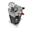
3.5 Fuel Delivery System Requirements
Fuel pressure directly affects how much fuel is delivered to the engine when the injectors are opened. Higher fuel pressure delivers more fuel during an injector opening event. Lower fuel pressure delivers less. It is critical that the fuel pressure matches the injector pulse widths required by the calibration for your specific application.
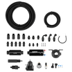
A complete high-pressure EFI fuel system must be installed for the Jackpot 2 LS System. The pump should be capable of supplying 255 liters per hour or 400 pounds per hour of fuel. The system requires a minimum of 43.5 PSI fuel pressure. Fuel pressure must be regulated between 43.5 PSI and 58 PSI. The system will not self-regulate fuel pressure and must be regulated by your fuel delivery system.
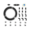
Required fuel system components:
● A 100 micron pre-filter (installed before the pump)
● A 10 micron post filter (installed after the pump)
● An EFI fuel pressure regulator (installed after the fuel rail)
Return Line Requirements
Your fuel delivery system may require a fuel return line to the tank. This depends on the location of the regulator and whether it is in-tank or external.
● If the regulator is external, a return line is required.
● Surge tank-style fuel pump modules also require return flow.
⚠️ WARNING: Some late-model vehicles originally equipped with a throttle body injection system may have a usable return line. However, the return line must not create a pressure restriction. Return line pressure should remain below 3 to 5 PSI and must be at least ⅜" in diameter. A restricted or undersized line can cause tuning issues.
⚠️⚠️ DANGER: Do not use vapor canister lines as fuel return lines. This can lead to fuel leaks, fire, or explosion, and may result in serious injury or death.
⚠️⚠️ DANGER: Proper installation of a return line may require complete removal of the fuel tank. This should be performed only by a qualified technician. Improper handling can cause an explosion or serious injury.
3.6 Minimum Tools Required For Installation
The following list is not comprehensive.
● Standard socket and wrench set
● Standard screwdriver set
● Standard allen wrench set
● Wire strippers
● Rags or shop towels
● Drill and assorted bit sizes
● Welder and PPE if welding the O2 sensor bung (not required when using a clamp-on method)
● Electrical connectors
● Up to a 2" hole saw (depending on ECU mounting location)
● Factory Service Manual for your vehicle and or engine
● Digital voltmeter
● Terminal crimping tool
An assistant is required for certain installation and adjustment procedures. For safety reasons, do not attempt to complete the installation alone.
4.0 Pre-Installation Steps
4.1 Removal of Existing Components
1. Disconnect the battery.
2. If applicable, remove the existing OEM system components according to your vehicle's Factory Service Manual.
⚠️ WARNING:Before disconnecting the battery, identify a clean, switched 12-volt ignition source. This source must provide 12 volts during cranking and when the key is in the run position.
4.2 General Checklist
☐ Conduct an inventory check to ensure you have all the necessary components and tools before beginning the installation process
☐ Ensure all mating surfaces are properly cleaned and sealed
☐ Ensure chassis and engine grounds are cleaned
☐ Make sure your battery is fully charged to a minimum of 12 volts and in good condition
☐ Ensure the vehicle has an adequate fuel level
☐ Ensure adequate hood clearance is available for manifold installation (if applicable)
☐ Ensure accessory drive compatibility with your intake manifold (if applicable)
☐ Ensure your exhaust system is free of leaks
5.0 Installation
This section covers ECU, Sensor & Wire Harness installation, as well as connecting sensors and coils to the harness.
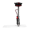
5.1 Fuel System Component Installation
1. Refer to the diagrams provided with your fuel system for correct component orientation and placement.
2. Install the pre-filter between the fuel tank and the pump inlet. Confirm that the arrow on the filter points toward the pump.
3. Install the post filter between the pump outlet and the fuel rails. Confirm correct flow direction. Check hoses for any sharp bends or kinks.
⚠️ WARNING:Flush all fuel lines before connecting or assembling the fuel system. Failure to do so may push debris into the injectors, causing them to become clogged.
⚠️ WARNING: Verify correct filter orientation. Incorrect installation will cause a malfunction.
5.2 Sensors Installation
The following items are the primary sensors that must be installed. Each connector on the main harness is labeled with its corresponding sensor name, shown in parentheses below.
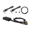
5.2.2 Wideband O2 Sensor Placement and Setup
Harness connectors: WBO2_1 and WBO2_2
Kit items required for this step:
● Wideband O2 Sensor (2)
● Weld-in O2 Sensor Bung (2)
Select the sensor location
● Install one wideband oxygen sensor in each exhaust bank where it can read the combined exhaust flow from that bank. In most header applications, the preferred location is just downstream of the point where the primary tubes merge into the collector.
● For long-tube headers, place the sensor approximately 6 to 10 inches (150 to 250 mm) after the collector. Position the sensor as close to the engine as practical while keeping it upstream of any catalytic converter so the ECU receives an accurate and timely AFR signal.
● Maintain enough exhaust pipe length after the sensor location to support a stable reading. A minimum of 18 inches (450 mm) of pipe downstream of the sensor is required, and 24 inches is preferred where space allows.
● If the exhaust system uses an H-pipe or X-pipe, install each sensor ahead of the crossover so each channel reads only its own bank.
● If the vehicle is equipped with an AIR or smog-pump system, the sensor must be installed where it reads untreated exhaust gas before any injected air enters the exhaust stream.


Sensor angle and clearance
● Mount the sensor in the upper half of the exhaust tube with the sensor body angled more than 10 degrees above horizontal. This helps reduce condensation exposure at the sensing element.

● Before welding the bung in place, verify that the connector and wiring will clear nearby components. Do not place the sensor where the harness may contact hot exhaust parts, moving components, or sharp edges.
● Route the sensor wiring away from primary tubes, collectors, and ignition wiring. Add heat protection where needed, and avoid running the wideband wiring in long parallel paths next to ignition leads or other high-interference circuits. If crossing is necessary, wires should intersect at an angle rather than running alongside each other.
Prepare and install the bung
● Mark the selected mounting point and create the opening required for the supplied bung.
● Fit the bung so the inside of the exhaust path remains as smooth as possible, with no lip protruding into the pipe.
● Remove burrs as needed, then weld the bung completely around its perimeter to create a leak-free seal.
● Allow the welded area to cool completely before installing the sensor.
⚠️Welding precaution
Before performing any welding on the vehicle, disconnect power from the EFI system and unplug related electronic components and harness connections that could be affected. When practical, remove sensitive control electronics from the vehicle before welding begins.
Install the wideband sensor
● If the sensor threads are not already pre-coated, apply a very small amount of nickel-based anti-seize to the threads only, following the sensor manufacturer's instructions. Do not allow anti-seize to contact the sensing tip.
● Thread the sensor into the bung and tighten it to approximately 22 to 33 ft-lb (30 to 45 N·m).
⚠️ WARNING: Never run the engine with a wideband sensor installed unless the sensor is connected to the ECU and being actively powered and heater-controlled. A wideband sensor must operate at an elevated temperature to function correctly. Running the engine with the sensor installed but unpowered can allow moisture and contaminants to collect inside the sensor, which may cause thermal shock, contamination, loss of accuracy, or permanent sensor failure.
Electrical connection
Install one sensor in the driver-side bank and connect it to the matching harness connector. Install the second sensor in the passenger-side bank and connect it to the remaining wideband connector. Always confirm the correct connector by the printed harness label before powering the system.
Warning
● Leaded fuel will shorten the wideband oxygen sensor life and is not recommended.
● Use only oxygen-sensor-safe sealants in nearby exhaust work. Some silicone-based products can release compounds that may damage the sensor.
● Eliminate any exhaust leaks upstream of the sensor location before attempting to verify AFR or tune the system, since leaks ahead of the sensor can distort the reading.
● For turbocharged applications, place the sensor 12 to 24 inches downstream of the turbine outlet. Do not install the sensor ahead of the turbocharger.
5.2.3 Intake Air Temp Sensor (IAT)
Install the IAT sensor into the air intake (before the throttle body) or at the bottom of the air cleaner.
Do not install the IAT sensor into the intake manifold, as heat soak will occur and cause false sensor readings. Plug the sensor into the harness connector labeled "IAT."
5.2.4 Manifold Air Pressure Sensor (MAP)
Your system will include one of two different MAP sensors, depending on your selected kit, and subsequently include one of two different sub-harnesses for the sensors. The Jackpot system is compatible with many other sensors, but you may need to configure the sensor calibration manually.
Option 1: 4 Pin Sub-harness
Used with the 1-bar AE1036 MAP Sensor and includes connectors for MAP, IAT, IAC, and TPS.
Option 2: 3 Pin Sub-harness
Used with the 2.6 Bar AE1036B TMAP Sensor and includes connectors for MAP, IAC, and TPS.
|
System |
Rating |
SKU |
Notes |
|
Standalone Systems |
2.6 Bar (TMAP) |
AE1036B |
Previously labeled AE1041 |
|
Manifold kits with 4-bbl throttle body (AM1004) |
1 Bar (MAP) |
AE1036 |
Previously labeled AE1040 |
|
Manifold kits with single-blade throttle bodies |
2.6 Bar (TMAP) |
AE1036B |
Previously labeled AE1041 |
● Install the MAP sensor into your intake manifold. The exact location may vary from manifold to manifold. Refer to the manifold manual to determine the correct location for installation.
● Connect the MAP sensor to the harness connector labeled "MAP."
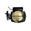
5.2.5 Throttle Position Sensor (TPS)
Install the TPS sensor into the throttle body and plug the sensor into the connector labeled "TPS."
5.2.6 Coolant Temp Sensor (Labeled CTS or ECT)
The coolant temperature sensor is not included with the kit, as they are pre-installed in most LS engines. Plug the CTS into the connector labeled either "CTS" or "ECT" (depending on the harness revision).
5.2.7 Fuel Pressure Sensor (FPS)
A fuel pressure transducer connector (optional) is pre-installed in the main harness and labeled "FUEL" or "FPS" depending on the system. If these are not connected to a pressure transducer, the fuel pressure shown on the handheld display will not be accurate. This should not cause any performance issues. Connect to the transducer (if installed).
5.2.8 Oil Pressure Sensor (OPS)
Connect to the factory oil pressure sensors located at the rear of the engine by plugging into the harness connector labeled "OPS."
Note: LS2 GTO & F-Body Oil Pressure sensors have a unique pin-out and cannot be used with the Jackpot 2 harness.
5.2.9 Camshaft & Crankshaft Sensors
Note: Your kit will come with both 24x and 58x sub-harnesses, and you must first determine which one your engine uses to ensure you use the correct one during installation.
The camshaft position sensor is used to calculate engine position. It is necessary for sequential fuel calculations. It senses a toothed wheel (reluctor wheel, reluctor ring, etc.) and converts this pattern into a voltage/frequency signal that the ECU uses for basic calculations.
The camshaft position sensor of LS engines is in one of two locations, depending on whether the harness is for a 24x or 58x reluctor wheel. If 24x, the camshaft position sensor is located on top at the rear of the block, at the back of the intake manifold. If 58x, the cam sensor is in the timing cover on the driver's side.
Note:For 58x, the Aces harness plugs directly into the sensor, not the short pigtail that may be on the engine.


● The crankshaft position sensor harness should be bundled in heat shielding for protection. The crankshaft position sensor is located behind the starter. It is imperative that this harness be routed away from heat sources.
● Plug the Camshaft sensor into the sub-harness connector labeled "CAM" and plug the Crankshaft Sensor into the sub-harness connector labeled "CRANK."
5.2.10 Knock Sensor Installation (Optional)
Note:If using knock sensors with your application, you must custom-program the ECU using the PC Software as the system is not set up to use the knock sensors by default.
Most applications do not require setting up the knock sensors in order to run properly, so this step is skipped by most users. This is an optional safety configuration feature.
Connect to the Knock Sensor(s) using the sub-harness pieces labeled "Knock." There will be an additional descriptor (labeled 24x or 58x) on the sub-harness label, which should be chosen based on your engine knock sensor location. Earlier model LS engines have knock sensors located in the center valley of the engine and use the 24x version sub-harness. Later model LS engines have knock sensors located on the bottom of the block near the oil pan rails and should use the 58x version sub-harness.
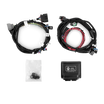
5.3 Wiring Harness Installation
This section explains how to properly install the wiring harnesses for this system and connect to the sensors you installed in the previous steps. An EFI system depends heavily on receiving a clean and stable voltage supply. The ground side of the electrical system is just as important as the power side. EFI ECUs contain multiple processing devices that require clean power and ground sources. Their wiring harnesses must be installed so they are separated from noisy or dirty power and ground sources.
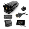
There are two potential methods for hooking up the main power, ground, and ignition sources to the system. Depending on the option you purchased, your system will come with either a PDM or a Relay Kit.
Wiring Connection Guide when using the Aces PDM (Power Distribution Module)
Refer to the full wiring diagram for the PDM + Jackpot combo, which is available on Aces' website by visiting https://acesefi.com/pages/support >> Support >> Downloads >> Manuals & Guides
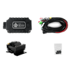
Wiring Connection Guide when using the Aces Relay Kit
● Refer to the full wiring diagram for the Relay Kit + Jackpot combo, which is available on Aces' website by visiting https://acesefi.com/pages/support >> Support >> Downloads >> Manuals & Guides
● Main Power & Battery Connection
○ Only use the supplied fused power cable with the correct connectors provided by Aces. Do not connect the power cable to the ECU until all wiring and installation are complete.
The following guidelines are applicable to both methods.
Wiring Requirements
EFI performance depends on clean power, reliable grounds, and careful harness routing. Connect the ECU's main battery feed and ground directly to the battery, and confirm that the battery, engine, and chassis have a strong shared ground path.
● Keep EFI wiring away from ignition components, plug wires, coils, ignition boxes, and other interference-producing circuits. Do not run sensor wiring alongside high-voltage or high-current wiring for long distances.
● Make all electrical connections with the correct tools and approved connection methods. Protect finished connections with heat shrink or equivalent sealing materials, and do not use shortcut splice connectors that are prone to failure.
● ECU outputs should be used only within their intended load limits. Devices such as cooling fans should be controlled through the proper relay or interface arrangement unless the output is specifically designed to carry that load directly.
● Do not share sensor signal wires between multiple controllers unless the circuit was intentionally designed for that purpose. Use a stable keyed 12V source for switched power, and avoid ignition-side or accessory circuits that may introduce voltage noise into the EFI system.
Harness Routing
If the ECU is mounted inside the vehicle, the main harness must be routed through the firewall into the engine compartment. If no existing pass-through is available, use a 2-inch hole saw to create an opening in the desired location. Install a grommet sized for a 2-inch hole to properly seal this area. One 1-inch grommet is included with your system.
If the ECU is mounted in the engine compartment, the cable for the user interface (the handheld or Bluetooth module) must be routed to the CAN connector on the main harness, which is located near the ECU main connector and labeled "CAN". If you want to access the handheld module after startup, the small CAN connector will need to be routed through the firewall to a convenient location inside the vehicle.
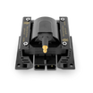
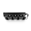
5.4 Ignition Coils
Connector Labels:"IGN_1357" & "IGN_2468"
The Jackpot ECU can support most OE and aftermarket smart coils, but Aces EFI recommends using the Aces GM LS Ignition Coils (SKU AC2011) for best performance. Connect the coil connectors on the harness to each ignition coil.
Connect the coil connectors to each bank of coils.
● The driver side connector is labeled IGN_1357.
● The passenger side connector is labeled IGN_2468.
Verify that each connector is plugged into the correct coil bank. Both connectors must plug into the detachable coil sub-harness (AH2011-2) in the correct positions.
⚠️ Warning: Incorrect placement will cause an incorrect firing order and may result in engine damage.
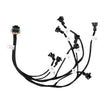
5.5 Fuel Injector Connection
Connector Labels: All are labeled in an "INJ_XX" format, where each number corresponds to the cylinder number.
Note:The Jackpot ECU is compatible with high-impedance fuel injectors only. For direct-drive operation, injector coil resistance must be greater than 8 ohms.
Reminder: Aces EFI recommends using a 58 psi base fuel pressure for LS engines.
The detachable injector sub-harness uses EV6 or EV1 connectors, depending on the option you purchased. If your LS engine uses an injector style such as Multec, you can purchase a Multec sub-harness from Aces or use adapters.
The Jackpot ECU uses sequential injection, so each injector connector must be plugged into the correct injector. Incorrect placement can cause improper fueling and may result in engine damage.
Connect the injector harness to the injectors for each cylinder.
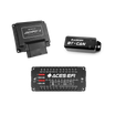
5.6 Handheld or Bluetooth Module Connection
Connector Label: CAN
The CAN connection is used for communication devices such as the handheld controller or Bluetooth module. These devices allow initial system setup, access to live EFI data, and certain user adjustments or monitoring functions.
● Mount or route the connection so the device can be reached from the passenger compartment during installation, startup, and configuration.
● Plug the handheld or Bluetooth module into the designated CAN connector on the main harness. Verify the connector label before making the connection.
● Once the system has been configured and the engine is operating correctly, the handheld does not need to remain connected unless continued monitoring or tuning access is desired.
5.7 Loose Wires (On main harness)
This section refers to the main loose wires attached to the main harness, with the following labels:
Instructions for connecting wires using the Relay Kit
"IGNSW" (Red)
Connect to a clean key-on and cranking 12V power source. This source must provide power when the ignition is on and must also remain powered while cranking. Verify this with a voltmeter, as not all ignition circuits provide power during cranking. This wire is located approximately 20 inches from the ECU connectors.
NOTE:Do not connect this wire to a dirty source such as an ignition coil.
"Main_Power +" (Red)
Must be connected directly to the wire on the relay pack labeled "Main 12V Out." This circuit powers the fuel pump and fuel injectors. When connected to the relay, this wire is protected by a fuse in a sealed fuse holder near the relay.
"Ground" (Black)
Must be connected directly to the negative battery terminal. Using a chassis ground can cause electrical problems. This wire is located approximately 20 inches from the ECU connector.
"Fuel_Pump" (Brown)
Connect to the wire on the relay pack labeled "Fuel Pump".
"Main_Relay" (Orange)
Connect to the wire on the relay pack labeled "Main Relay".
"Tach Out" (Gray)
Provides a 12V square-wave signal used to trigger a conventional tachometer.
"Pump" (Orange)
This wire supplies power for the fuel pump and is located on the relay. Do not use this wire to power pumps that draw more than 15 amps. Refer to the fuel pump manufacturer for current requirements. For high-current pumps, use this wire to trigger a separate relay, and run a larger gauge wire (10 gauge recommended) to power the pump. The fuel pump also requires a ground wire. Run a ground from the negative pump terminal to a solid chassis or frame ground.
5.8 PDM Installation
⚠️ WARNING: Do not run ignition coils off of the PDM. Doing so may damage the system.
Step 1: Mounting the PDM
● Mount the PDM securely using the mounting holes provided.
● Choose a location that is dry, protected, and easy to service.
● Keep the unit away from exhaust heat, water exposure, and moving components.
Step 2: Connect Main Battery Power and Ground
● Connect "VBAT: to the battery positive.
● Connect "GND" to battery negative or to a verified chassis ground of equal electrical quality.
Keep both the power feed and the ground path short, direct, and appropriately sized for expected current.
Step 3: Connect Ignition Key Input
Connect a true ignition-on source to "IGNKEY". This source should remain active during engine cranking. Do not use an accessory-only circuit that drops out during starting.
When IGNKEY is active, the PDM energizes:
● IGNSW1
● IGNSW2
● IGNSW3
These outputs provide clean switched power for supporting circuits.
Step 4: Connect ECU Main Power
● Use "VMAIN1", "VMAIN2", and/or "VMAIN3" for the ECU main power path as required by the system design.
● Use "MRD" as the main power control input for the VMAIN outputs.
● Follow the system wiring plan to determine which VMAIN outputs are used by the ECU and related circuits.
Step 5: Connect Fuel Pump Circuit
● Use "VPUMP" as the fuel pump power output.
● Use "RPUMP" as the fuel pump control input.
● Verify actual fuel pump current draw before final connection. The fuel pump circuit must remain within the 15 A maximum rating of VPUMP.
Step 6: Connect Fan Circuits
● Use "RLY1" and "RLY2" as control inputs for relay-fed fan stages or related switched circuits as required by the application.
● Use "VRLY1" and "VRLY2" as the corresponding relay-power outputs.
● Each of these outputs is limited to 10 A maximum, and both share fuse F1.
● If a fan motor or fan stage exceeds the available PDM channel capacity, use the PDM output to trigger an appropriately rated external relay rather than powering the fan motor directly from the PDM.
Step 7: Connect Auxiliary/AC Fan Circuit
● Use "RFAN" as the control input for the auxiliary fan circuit.
● Use "VFAN" as the corresponding fan power output.
● VFAN is limited to 10 A maximum.
Step 8: Connect Relay-Fed Accessories
Use "VRLY1" and "VRLY2" for controlled relay-fed accessories where needed. These outputs are suitable for devices such as auxiliary pumps, secondary fans, or other switched accessories when used within their rated limits.
Step 9: Connect Tachometer/POINT Circuit
Use "POINT" for tachometer signal routing. Treat the POINT circuit as a signal path only. It is not a load-power output.
5.9 Additional/Auxiliary Wires Harness
This section refers to the sub-harness of colored wires. These wires can each be connected as needed to auxiliary items.
"Main 12V Out" (Red)
Provides a 12V power supply from the main relay.
"Fan 1" (Purple)
Provides a ground output to trigger a relay for a cooling fan. Do not connect directly to a fan. Connect to the ground trigger side of the relay.
"Fan 2" (Green)
Provides a ground output to trigger a relay for a cooling fan. Do not connect directly to a fan. Connect to the ground trigger side of the relay.
"Burn" (Yellow)
This wire is for a burnout rev limiter input. Supplying 12V to this wire signals that a burnout control has been activated.
"Launch" (Blue)
Launch rev limiter input. Supplying 12V to this wire signals that a launch control has been activated.
"Charging" (Red)
Provides 12V power to the alternator (Pin F).
"Brake Switch" (Brown)
Connect to the brake light switch, which provides +12V and unlocks the torque converter while the brakes are applied.
"VSS +" (Blue)
Vehicle speed sensor input for non-computer-controlled transmissions.
"VSS -" (Black)
Vehicle speed sensor input for non-computer-controlled transmissions.
"Fuel Level" (Purple)
Fuel level sensor input. Accepts a sender resistance range of 0-250 ohms or 250-0 ohms and converts this to a percentage of fuel remaining in the tank.
"Nitrous In" (Brown)
This wire needs to be supplied with a 12V power source while nitrous is active. This will retard timing when nitrous is activated.
"VSS Out" (Brown)
Provides a VSS signal for aftermarket gauges. Cannot be used while using transmission control features.
"Custom 12V" (Yellow)
User-defined external 12V voltage signal input. Typically used to execute an action after a 12V voltage signal is input, such as activating a user-defined relay terminal.
"Ground Trigger" (Blue)
The ECU controls whether the terminal is connected to the battery negative. Maximum operating current: 0.6 A.
"Relay" (Black)
The ECU controls whether the terminal is connected to the battery negative. Connect to the relay negative. Maximum operating current: 0.6 A.
"S5V" (Red)
S5V provides 5V power supply for external sensors. Maximum output operating current: 1 A.
"Sensor-Ground" (Black)
Supplies ground for aftermarket pressure sensors.
5.10 Transmission Harness (Select kits only)
Transmission Wiring
The transmission harness can be used with the following GM 4-speed transmissions:
● 4L60E (1996-2003)
● 4L65E (1996-2003)
● 4L67E (1996-2003)
● 4L80E (1994-2003)
Each connector is labeled for easy identification.
Transmission ECU Connector
Plugs into the connector on the Jackpot main wiring harness. This is the last connector opposite the main harness.
Main Transmission Connector
Plugs into the transmission connector located either:
● On the driver side of the 4L80E (horizontal orientation). On 4l80E transmissions, the transmission connector must be rotated such that the arrow is positioned at the top and not facing downward when plugged in.
● On the passenger side of the 4L60E (vertical orientation). On 4L60E transmissions, the transmission connector must be rotated such that the arrow is positioned facing the right side of the vehicle when plugged in.
Vehicle Speed Sensor (VSS) / Transmission Output Speed Sensor (OSS)
Located on:
● The rear driver side of a 4L80E
● The rear passenger side of a 4L60E
Turbine Speed Sensor (TSS)
The 4L60E does not use a turbine speed sensor. On 4L80E applications, the TSS is located toward the front driver side of the transmission.
NOTE:The 4L70E has an internal TSS, but it does not connect to the Jackpot harness. The TSS is not used for ECU calibration and is only available for monitoring.
5.11 Drive-By-Wire Harness (Select kits only)
⚠️ Warning: Use only the unmodified drive-by-wire wiring harness supplied by Aces. This harness must not be cut, shortened, lengthened, tailored, or modified for any reason. The harness contains protective shielding and grounded cabling to ensure proper operation. Do not remove or modify the protective sheathing.
Aces assumes no liability for any issues arising from the use of throttle pedals, throttle bodies, or related components that are not specifically approved by Aces Fuel Injection.
Overview
The Jackpot ECU has built-in capability to control OEM-style drive-by-wire throttle pedals and throttle bodies for aftermarket installations.
Installation
⚠️ Warning:
● The throttle body must be installed so that the throttle plate or plates can rotate freely without any interference or binding.
● The pedal assembly must be mounted securely and rigidly, without placing the pedal or its components in a bind or applying mechanical stress to the electrical and electronic parts. Proper pedal position is critical.
● The accelerator pedal must have adequate clearance throughout its full travel so that it cannot contact any object that would prevent it from returning to the idle position when released. The pedal must be mounted far enough from the brake pedal so the brakes can be fully applied without the driver's foot contacting the drive-by-wire pedal.
● The drive-by-wire pedal should sit lower than the brake pedal when the brake pedal is fully depressed.
Wire Harness Installation
● Install the wiring harness supplied by Aces so that there is no possibility of the wiring being cut, pinched, or abraded. Use rubber grommets wherever the harness passes through a firewall or sheet metal panel.
● The drive-by-wire harness must not be routed near noisy electrical components or wiring that may emit RFI or EMI. Common noisy components include spark plug wires, ignition coils, high-energy ignition boxes, and audio equipment such as radios or CB units. Maintain at least 5 inches of clearance from these components and their wiring.
● The harness is designed to be plug-and-play with the throttle bodies and pedal assemblies listed below. It must not be used for other applications.
System Safety
IMPORTANT: Installation of the safety circuit described in this section is required when using the drive-by-wire feature. Failure to install this input is done at the user's own risk. The user assumes all liability for any damage or unsafe operation that may result from incorrect installation of the drive-by-wire harness. .
Most drive-by-wire systems use two position sensors: one in the throttle body and one in the accelerator pedal assembly. This redundancy provides a failsafe in case one sensor fails.
Aces Jackpot EFI systems require both sensors to operate correctly. If either sensor moves outside its calibrated position, the ECU immediately removes power from the throttle body and allows it to move to its factory "limp home" position as described below.
Throttle Body Limp Home Position
Factory drive-by-wire throttle bodies have a limp home position. This is the position of the throttle blade when no power is applied to the throttle body.
In this position, the throttle body allows enough airflow for the vehicle to move at approximately 45 mph under typical conditions. This value varies by manufacturer but is typical for the GM throttle bodies supported by this harness.
This position allows more airflow than is required for idle. If the throttle body enters the limp home position due to a sensor failure or any other issue, the engine will receive more air and will produce more power than at idle. When the vehicle is in gear, additional brake pressure may be required to keep the vehicle from moving.
Wiring Harness
LS engines use two styles of drive-by-wire throttle body connectors:
● An 8-pin connector (early truck applications)
● A 6-pin connector (passenger car and 2007 and later truck applications)
Wire the DBW Sub-harness as follows:
1. ECU connector: Plug into the main connector on the Jackpot wire harness labeled "ETC".
2. Pedal connector (Labeled "PPS"): Plug into the throttle pedal assembly.
3. Throttle body connector (labeled "ETC"): Plug into the drive-by-wire throttle body.
WARNING: The brake switch input is required for proper safety operation and is located on the additional/auxiliary wire sub-harness. Connect this to a +12V input from the brake pedal switch.
Approved Components
The following drive-by-wire throttle bodies and pedal assemblies are supported by Aces Jackpot LS EFI kits.
Approved GM throttle bodies:
● GM part number 12570800
● GM part number 12570790
● GM part number 12580760
● GM part number 12580195
● GM part number 12605109
● GM part number 12629992
Approved throttle pedal assemblies:
● GM part number 10379038
● Lokar part number BDBW-GM02
5.12 ECU Installation
The ECU may be mounted inside the passenger compartment or in the engine compartment. If mounting in the engine compartment, follow these guidelines:
● Mount the ECU where water or road debris will not strike it directly. Do not mount where the ECU can be pressure-washed or submerged.
● Keep the ECU away from major heat sources. Do not place it near exhaust manifolds or headers.
● Keep the ECU as far as reasonably possible from sources of electrical noise, such as spark plug wires, capacitive discharge ignition boxes, and similar devices.
● Orient the ECU with the connector end pointing down so water cannot enter the terminals. If the harness route prevents this, include a drip loop in the wiring below the connector.
● Do not overtighten the mounting hardware, especially if the ECU is not on a perfectly flat surface.
● Use vibration isolation when possible. Your kit includes four rubber feet. Install the ECU with these rubber feet or equivalent isolation pads.
● Mount to a rigid metal surface using four M5 screws and flat washers.
● Route the wiring harness away from sharp edges and moving parts. Use grommets where the harness passes through bulkheads.
6.0 First Power On & System Setup
Upon connecting all wiring harnesses, the installation of the EFI system is complete. The Engine Control Unit (ECU), handheld controller or Bluetooth module, throttle body and intake hardware, all sensors, wiring, fuel pump, regulator, and return line (as applicable to the fuel system type), and all other requisite hardware should now be installed and connected. The vehicle should be ready to start and run. If the system is not ready, consult any supplementary hardware installation manual(s) provided with your specific system.
6.1 First Power On
Turn the ignition key to the run position, but DO NOT crank the engine yet. This should apply power to the ECU as well as to the Aces handheld or Bluetooth module. The handheld should power up and display the home screen. If you are using the Bluetooth module and app, refer to the Bluetooth module manual found on our website at acesefi.com.
At this time, you should hear the fuel pump cycle on and run for approximately 5 seconds.
IMPORTANT: Check for fuel leaks before moving forward to the next step of setting up your system.
With your handheld or Bluetooth module powered up, the first screen you should see is the system select screen. Scroll left or right to find the Jackpot 2 system and double-click it to select it.

Once you select your system, it will take you to the home screen, where you will see the initial gauge and sensor reading layout. You should briefly see a blue banner at the top of the screen letting you know it connected to the ECU successfully. If you see a persistent yellow banner indicating a connection fault or timeout, please follow these steps before proceeding:
1. Make sure the system you bought is indeed the Jackpot 2.
2. Make sure you have selected the appropriate system in the handheld. It should say "Jackpot 2" at the top of the screen while on the home page. If it does not say Jackpot 2, then click the gear icon in the top right corner, click "Settings", click "System Select", and scroll to find the Jackpot 2 and double click it.
Once your handheld connects to the ECU successfully (no flashing error message showing on the home screen), you can begin the wizard setup.
6.2 Startup Wizard
The next step is to run the Startup Wizard, so the system can begin learning and building the fuel maps. The self-learning function performs best on stock to mild engine combinations, such as camshafts with a lobe separation angle of 110° or greater and engines producing approximately 200-375 horsepower. For more aggressive engine combinations, the self-learning feature alone may not provide optimal results, and manual tuning may be required.
Basic Navigation & Adjustment Methods
Before running your startup wizard, here are some basic interaction methods you should become familiar with to more easily make adjustments during the wizard process and afterwards. Depending on your system, you will interact with and set up the Jackpot 2 EFI system using either an Aces handheld controller or a Bluetooth module with the Aces app. Whether you use a supported handheld or the app, they will all provide access to the same basic functions and menus.

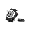
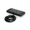
Aces 5" HD Handheld (3rd gen) shown
The handheld is a color touchscreen device that connects to the harness via a CAN bus cable. Screen sizes may vary by kit, but operation is the same across all versions. The Bluetooth module allows you to perform the same functions using a compatible mobile device and the Aces EFI app.
After connecting to the ECU, the handheld or app allows you to monitor and adjust key system parameters, including:
● Idle speed settings
● AFR (air fuel ratio) targets
● Fuel pump settings
● Basic startup and drivability parameters
Real-time data such as engine speed, coolant temperature, throttle position, and lambda can be viewed on live data screens for monitoring and basic diagnostics.
Use the touchscreen or on-screen menus to move between the home screen, setup wizards, tuning menus, and live data views.
Making Adjustments
Below are the various methods for adjusting parameters or setting data points. We will use the example of adjusting your Fuel Prime Percent to demonstrate how to use each of these methods.
1. Slider Bars
By default, for most settings, a slider bar will be shown. Slide the circle on the bar left or right, or click the "-" or "+" buttons on the touchscreen to adjust the parameters. Click the save icon in the top left corner to save the adjustment or click the return button in the top right corner to cancel saving.

2. Numeric Keypads
To display a numeric keypad and enter a more specific data point, click the edit box (the area where the number "100.0%" is being displayed above the sliding bar) to display a keypad. Once you enter the desired data point here, you can click "OK" to save or "Cancel" to cancel saving.

3. 2D Graphs
Drag the red dot on the graph or click the mechanical buttons on both sides to adjust the parameters. The y-axis coordinate value of the currently adjusted parameter will be displayed in the upper right corner. The four buttons on both sides of the interface will disappear after a short delay. Clicking the two mechanical buttons at the lower left corner can switch the position of the green dot, clicking the button at the right center can raise the position of the green dot, and clicking the mechanical button at the lower right corner can lower the position of the yellow dot. The y-axis coordinate value of the green dot is displayed in the upper-right corner of the interface.

6.3 Wizard Setup
|
|
Home Screen Click the " |
|
|
Main Menu Click on "Wizards." |
|
|
Wizards Click "Start Wizard" to begin initial configuration and set base parameters. You can click the left and right arrows to go to the next step or go back at any point during the wizard. |
|
|
Select Display Unit 1 Choose to view parameters in either Imperial Units or Metric Units. (e.g., PSI vs. kPa) Press " |
|
|
Select Display Unit 2 Choose to view parameters in either AFR values or in Lambda values. |
|
|
Engine Type Select GM LS. |
|
|
Crankshaft Type Select 24x or 58x depending on your engine. |
|
|
Camshaft Type Select your camshaft type: Stock: This selection will work well on most applications equipped with stock or "street performance" camshafts. Mild: Used for mild profile camshafts. i.e., about 7 PSI vacuum or about 50 KPA Race: Rarely used option for very aggressive engine builds. Press " |
|
|
MAP Type Choose the appropriate MAP sensor. If you are using another sensor, select it now. |
|
|
Dual WBO2 Option All Jackpot Systems (except for Jackpot Lite and Jackpot TBI) will come with 2 WBO2 sensors. You can choose to use one or both, and you can indicate so during this step and press " |
|
|
Drive by Wire Select "Yes" if you are using an electronic throttle body or select "No" if you are using a cable driven throttle body. Press " |
|
|
Transmission Control Select "Yes" if you need trans control for a 4L60E or 4L80E transmission; otherwise, select "No" if you are running a manual transmission or Press " |

 " icon in the upper right corner to enter the Main Menu.


 " to continue.


7.0 Initial Start-up/Engine Run
The system is now ready for its first start-up.. Turn the key on, but do not crank the engine. Verify the following readings on the handheld or app:
☐ MAP: Around 14
☐ Temperature Readings (ECT & IAT):Near ambient temperature
☐ TPS:0
☐ Battery Voltage: Minimum of 12.5 volts
Once these values are confirmed, you can proceed to crank the engine. After the engine starts, confirm the following:
☐ No coolant, oil, or fuel leaks
☐ No wiring contacting headers or other hot components
☐ Cooling fans are operating normally
Allow the engine to reach operating temperature. While the vehicle is in park, gently rev the engine several times, keeping engine speed below 2,500-3,000 RPM. Repeat this process 2-3 times. After the engine has reached operating temperature and the initial checks are complete, the vehicle can be driven. It is recommended to drive the vehicle approximately 5-10 miles to allow the ECU to begin completing the initial self-learning process.
8.0 Troubleshooting
The following section outlines common issues that may occur during installation or initial startup and provides basic checks to help identify the cause.
|
No start |
If the engine does not start, verify the following: ● Battery voltage is above 12 volts ● Main power and ground connections are secure ● Fuel pump is operating and fuel pressure is present ● Ignition system is properly connected ● Crank signal is being detected by the ECU ● TPS is reading 0 at idle |
|
Inconsistent Exhaust Temperatures |
Large differences in exhaust temperature between cylinders may indicate a fueling or ignition issue. ● Verify injector connectors are fully seated ● Check for vacuum leaks at the intake manifold ● Confirm ignition wires are connected to the correct cylinders ● Inspect spark plugs for fouling or damage |
|
Running Too Lean |
If the engine appears to be running lean: ● Verify adequate fuel pressure ● Check for vacuum leaks ● Confirm injectors are connected and operating ● Verify the fuel pump wiring and operation |
|
Running Too Rich |
If the engine is running excessively rich: ● Check the fuel pressure regulator operation ● Verify injector connectors are correct and not swapped ● Inspect temperature sensor readings for accuracy ● Confirm MAP sensor readings are reasonable. At sea level, this should be around 4-5 PSI. |
|
Lean Bog |
A lean bog during throttle input may be caused by: ● TPS is not calibrated correctly ● Low fuel pressure ● Vacuum leaks ● Improper ignition timing |
|
No Spark |
If there is no spark: ● Verify ignition coil connections ● Confirm ignition module or distributor wiring ● Check crank trigger or distributor signal ● Ensure the ignition output is configured correctly in the ECU |
|
No Fuel Pressure |
If fuel pressure is not present: ● Verify the fuel pump is receiving power ● Check the fuel pump relay and fuse ● Inspect fuel pump wiring ● Confirm the fuel pump ground connection ● Ensure the fuel lines are properly connected |
If issues persist after performing the checks above, please contact Aces EFI Technical Support at acesefi.com or +1 (423) 590-2237 for further assistance.