

Table of Contents
Command Center 2 Installation Guide
Download PDF here: Command Center 2 Installation Guide V2.0
Overview
The Command Center 2 can be used in conjunction with any EFI system. It uses your stock fuel tank, stock carburetor, fuel pump, and stock inlet fuel lines. This manual will guide you through the process of inserting the Command Center 2 into your engine's fuel plumbing.
Critical Warnings
⚠️ WARNING: Failure to follow these instructions may result in an improper installation, which could cause serious injury, death, or property damage. Improper installation or misuse of this Aces product will void all warranties.
⚠️ WARNING: Installation, adjustment, and repair should only be performed by a trained mechanic with adequate experience in fuel and automotive electrical systems.
⚠️ WARNING: Aces EFI systems consist of multiple sophisticated components. Failure of a single component does not justify a warranty claim for the entire system. Individual components are available for warranty replacement.
⚠️ WARNING: To preserve the warranty, these installation instructions must be read and followed thoroughly. Failure to follow instructions can void the warranty and may result in serious injury or property damage.
⚠️ WARNING: Fuel vapors are heavier than air and can accumulate in low areas, where they may be ignited by sparks or flames, resulting in property damage, injury, or death. Always prevent fuel spills to eliminate this risk.
⚠️ WARNING: Work must be performed in a well-ventilated area. Do not smoke or have open flames nearby, as gasoline vapors are highly flammable and can cause explosions.
⚠️ WARNING: Aces EFI systems offer extensive adjustability, and proper setup and calibration are essential for safe operation. If you are not comfortable with engine fundamentals and EFI tuning, we recommend having the system installed and calibrated by an Aces authorized installer or qualified tuning shop. Our technical support team is also available at acesefi.com or +1 (423) 590-2237 to help answer basic installation, setup, and troubleshooting questions.
Kit Contents:
The Command Center 2 is available for purchase with or without a PTFE plumbing kit, labelled as AF4004. This guide assumes that you are installing the unit using the AF4004 kit, but the procedures are applicable to any setup.
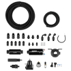
The AF4004 kit includes:
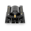
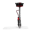
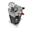
● (1) Command Center 2
● (5) PTFE hose fitting, black, -6AN straight
● (4) PTFE hose fitting, black, -6AN 45°
● (1) Fuel tank return fitting kit
● (1) 6AN nylon PTFE fuel hose 20ft
● (2) Ring terminal, insulated crimp #10
Note:The AF4004 kit does not include in-line fuel filters, which must be installed in the inlet and outlet lines. 30- and 100-micron inline filters are available for purchase at acesefi.com .
Installation
● Locate a suitable spot to install the Command Center 2. It may be mounted on the firewall or the frame, and must be installed within five feet of the throttle body for the included hosing to reach.
● Ensure there is space to install a pre-filter in the inlet fuel line between the fuel tank and the fuel pump, and a post-filter in the outlet fuel line that runs from the Command Center 2 to the EFI throttle body.
● It is recommended to mount the Control Center 2 vertically to avoid fuel starvation, but other orientations are possible. Mounting may be achieved using the four slotted holes located on the base flange or the four tapped M6 holes on the side of the end caps.
⚠️ WARNING:If using a carburetor or EFI pump to supply the Command Center 2, ensure that is not regulated and allows free fuel flow without restrictions. A 100 micron pre-filter must be installed prior to the inlet of the Command Center 2.
⚠️ WARNING:Ensure that your gas tank is equipped with a vent prior to installation. Failure to ensure two-way airflow may result in pressure build-up and vapor lock.

Fuel Plumbing

Fuel Hose Lengths
Determine the requisite hose lengths. Three separate lengths are required:
1. A line from the stock fuel pump to the Command Center 2
2. A line from the Command Center 2 to the outlet filter (not included)
3. A line from the outlet filter to the fuel injection throttle body
The hose ends must be cut square and clean using a razor-sharp blade. For hose end installation, secure the hose end in a vise, utilizing material to protect the finish. Avoid overtightening, as excessive clamping force may result in damage to the hose ends.
Given the variety of potential fuel plumbing configurations, the following is one recommended hose routing example. The suggested fitting configuration is as follows:
● Command Center 2 to Fuel Filter Line: Use a straight hose end at both the Command Center 2 connection and the fuel filter connection.
● Fuel Filter to Throttle Body Line: Use a straight hose end at the filter and a 45° hose end where it connects to the throttle body.
● Stock Fuel Pump to Command Center 2 Line:Use a straight hose end at the stock fuel pump connection and a 45° hose end at the Command Center 2 inlet.
This configuration is intended as a suggested starting point; you must carefully plan your specific plumbing and fitting requirements.
Fuel Tank Return Line
The return line is a critical part of the Command Center 2 installation and is not optional. A fuel-rated hose or hard line must be routed from the return fitting back to the fuel tank. If your vehicle is equipped with a pre-existing return line with a diameter of ⅜" or more, the Command Center 2 can be spliced into it. Otherwise, you can use the Fuel Tank Return Fitting included in your kit to connect the return line to the fuel tank.
⚠️ WARNING: Ensure that the return line is properly fitted to the fuel tank. Do not route the return line to open air.
Plumbing Stock Fuel Pump to the Command Center 2
Stock fuel pumps may have a steel tube outlet. If so, slide one end of the supplied -6 hose over the tube and secure it with a hose clamp. Other pumps have a threaded outlet port. If this port uses a barbed fitting for the stock fuel hose, this fitting can be reused. If the pump has a hard line exiting the outlet port, remove the threaded fitting and replace it with a steel adapter fitting that has male threads compatible with one of the supplied -6AN hose fittings.
Plumbing the Command Center 2 to the Throttle Body
Install the hose lengths you measured previously, connecting the Command Center 2 to the fuel filter and the filter to the throttle body.
Wiring
Positive (+)
Connect the power wire for your fuel pump from your ECU/controller to the positive (+) terminal on the Command Center 2. Determine the proper length for the wire but do not connect this wire to the Command Center 2 yet.
⚠️ WARNING:Ensure that the system is primed before the power wire is connected. Failure to do so risks damaging the system. The priming procedure is detailed below.
Insulate the exposed wire end with electrical tape to prevent inadvertent contact with any metal surface. When using this kit with an Aces EFI system, EITHER the loose black wire labeled "Pump" from the Aces EFI system, or the R-pump wire from the PDM must be connected to the positive terminal of the pump. Use an extension wire if the existing wire length is insufficient to reach the terminal.
Negative (-)
Connect a ground wire from the negative (-) terminal on the Command Center 2 to the PDM or the negative battery terminal.
⚠️ WARNING:A proper ground connection is essential for pump operation. Failure to ensure a ground connection could lead to system damage or electrical fire.
Fuel Pressure Regulator, Supercharger, or Turbocharger
The Command Center 2 has a built-in fuel pressure regulator mounted to the top. This regulator is not adjustable but is pre-set to provide 58 psi of fuel pressure to the EFI system. The regulator has a vacuum nipple on it, which is left open unless you are using the Command Center 2 on an engine with a blow-through supercharger or turbocharger. In that case, a vacuum hose should be run from the regulator to a non-ported vacuum nipple on the throttle body.
The Command Center 2 is compatible with all Aces EFI systems, as well as most aftermarket systems. The required connection for the regulator's vacuum port depends on the design of the specific EFI unit:
● Throttle body injectors (under the throttle blades): Connect a vacuum hose from the regulator to a ported nipple on the throttle body.
● Throttle body injectors (above the throttle blades): Leave the regulator's vacuum port open.
● Port injection systems (injectors in the manifold): Connect a vacuum line from the regulator to a ported nipple on the throttle body.
● Engine with a Roots supercharger:
○ If the injectors are under the throttle blades, connect a vacuum hose between the regulator and the throttle body.
○ If the injectors are above the throttle blades, leave the regulator's vacuum port open.
Note: Some aftermarket EFI systems may require a separate 43.5 psi (3 BAR) fuel pressure regulator.
Fuel Pressure Gauge on Sump Tank
The outlet gauge will indicate the fuel pressure being supplied to the EFI. The expected reading is approximately 58 psi.
Priming the Command Center 2
Reconnect the negative battery cable. Do not connect the Command Center 2 fuel pump power wire yet. This omission prevents the engine from starting during the priming procedure. Turn the ignition key to the "ON" position and crank the engine for ten seconds. Turn the key to the "OFF" position and wait 30 seconds. Repeat this procedure to ensure the sump tank is filled. This process allows the stock fuel pump to transfer fuel to the Command Center 2, but the Command Center 2 will not pump fuel to the EFI throttle body.
Inspect the entire fuel system for leaks before attempting to start the engine.
⚠️ WARNING:A 100-micron fuel filter mustbe installed between the stock fuel pump and the Command Center 2. Failure to do so could result in debris entering the tank, resulting in system damage.
⚠️ WARNING:The fuel pump power wire is live; do not connect it until the Command Center 2 has been primed.
Installing the Fuel Tank Return Fitting
The Fuel Tank Return Fitting provides a threaded hole in the fuel tank without having to reach inside the tank.
⚠️ WARNING:Before installing the return fitting, ensure the fuel tank is clean and free of debris and/or vapors. Failure to do so may result in serious property damage or bodily harm.
● Begin by utilizing a step drill to create a 1/2-inch diameter aperture in the fuel tank, positioning the hole towards the top of the tank.
● After drilling, remove any debris and ensure the aperture is free of burrs. Next, insert the bung and gasket into the hole.
● Thread the bolt with a washer into the bung. While stabilizing the bung with a 1-inch wrench, rotate the bolt clockwise to cause the bung to collapse and secure itself against the interior wall of the tank.
● Once the bung is seated (indicated by a noticeable increase in bolt rotation resistance), remove the bolt and washer.
● Finally, install the -6 ORB return fitting by holding the bung with a 1-inch wrench and rotating the fitting with a 9/16-inch wrench.
Proper installation is illustrated below:

Insert fitting with gasket, screw, and washer.

Twist bolt to collapse and set bung.

Bung installed.

Install ORB fitting.

Finished installation.
⚠️ WARNING:The fuel tank on your vehicle must be vented to avoid pressure build-up. Do not attempt to install or operate an EFI system without a properly vented fuel tank.