

Welcome back to another Setting Spotlight, Aces people. Today we have a whole new batch of variables available for your tuning pleasure. If you’d like to fiddle with these yourself, our Gen 2 PC Tuning Software is finally here, making tuning and calibration easier than ever. And as always, these variables will soon be searchable in our Settings Glossary, so they'll always be at your disposal.
Let’s get right into it!
-
MAP Acceleration Decay Rate:
Controls how quickly MAP-based acceleration enrichment fades at each temperature.
Increase values for a faster decay or decrease them to keep enrichment longer; adjust when the initial response is correct but the mixture afterward is not. -
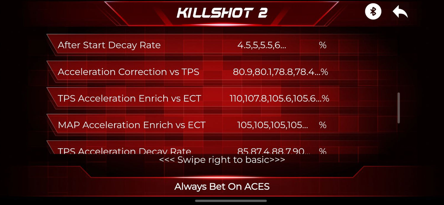
MAP Acceleration Enrich vs ECT:
Sets MAP-based transient enrichment versus coolant temperature.
Increase values where rapid load changes go lean, especially when cold; decrease them where the engine becomes too rich during the same transition. -
MAP Trans Fuel Table Gain:
Scales the overall MAP-rate acceleration-enrichment table.
Increase it if rapid load changes cause a lean stumble, or decrease it if those transitions are too rich; tune after the MAP sensor and base fuel table are correct. -
MAP x Point:
Defines the manifold pressure/load breakpoints used by this table (kPa).
Change these points to place more table resolution in the operating range you need to tune; keep them in ascending order and then review the table values after changing the axis. -
MAT Fuel Enrichment:
Adds or removes fuel based on intake-air temperature.
Adjust it only when logs show a repeatable fueling error as air temperature changes; avoid using it to mask an incorrect air-temperature sensor calibration. -
MAT x Point:
Defines the intake-air temperature breakpoints used by this table (°C).
Change these points to place more table resolution in the operating range you need to tune; keep them in ascending order and then review the table values after changing the axis. -
Mild Fuel Table Offset:
Applies an overall fuel offset to the corresponding cam/base fuel profile.
Increase it to add fuel across that profile or decrease it to remove fuel; use only for broad correction, then refine individual VE cells. -
Mild VE:
Defines volumetric-efficiency/fuel-model values across RPM and load for the selected base profile. Higher values command more fuel and lower values command less.
Tune cells from wideband data after injector, displacement, pressure, and sensor settings are correct. -
Min Fuel PW:
Sets the minimum injector pulse width allowed by the ECU across operating conditions.
Raise it only to stay above an injector's unstable minimum, or lower it when the current limit causes overly rich operation at very low fuel demand. -
Race Fuel Table Offset:
Applies an overall fuel offset to the corresponding cam/base fuel profile.
Increase it to add fuel across that profile or decrease it to remove fuel; use only for broad correction, then refine individual VE cells. -
Race VE:
Defines volumetric-efficiency/fuel-model values across RPM and load for the selected base profile. Higher values command more fuel and lower values command less.
Tune cells from wideband data after injector, displacement, pressure, and sensor settings are correct. -
Rev y:
Defines the engine-speed breakpoints used by the target-AFR strategy.
Change them only to redistribute tuning resolution across the RPM range, keep the points in ascending order, and review the related AFR table afterward. -
RPM y Point:
Defines the engine speed breakpoints used by this table (RPM).
Change these points to place more table resolution in the operating range you need to tune; keep them in ascending order and then review the table values after changing the axis. -
Stock Fuel Table Offset:
Applies an overall fuel offset to the corresponding cam/base fuel profile.
Increase it to add fuel across that profile or decrease it to remove fuel; use only for broad correction, then refine individual VE cells. -
Stock VE:
Defines volumetric-efficiency/fuel-model values across RPM and load for the selected base profile. Higher values command more fuel and lower values command less.
Tune cells from wideband data after injector, displacement, pressure, and sensor settings are correct. -
System Default VE:
Defines volumetric-efficiency/fuel-model values across RPM and load for the selected base profile. Higher values command more fuel and lower values command less.
Tune cells from wideband data after injector, displacement, pressure, and sensor settings are correct. -
Target AFR Type:
Selects how the ECU determines target AFR, such as fixed idle/cruise/WOT values or a full RPM/load table.
Choose the mode that matches the desired tuning strategy, then confirm the corresponding target settings are configured. -
Target Air/Fuel Ratio:
Defines the commanded air/fuel ratio across engine speed and load. Higher AFR values are leaner and lower values are richer.
Change cells to match the engine's idle, cruise, and power requirements while verifying results with a calibrated wideband. -
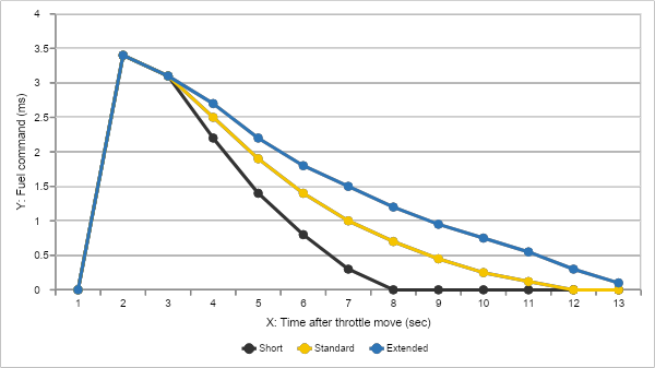
TPS Acceleration Decay Rate:
Controls how quickly TPS-based acceleration enrichment fades at each temperature.
Increase values for a faster decay or decrease them to keep enrichment longer; adjust when tip-in is correct but the mixture stays rich or goes lean immediately afterward. -
TPS Acceleration Enrich vs ECT:
Sets TPS-based transient enrichment versus coolant temperature.
Increase values when quick throttle opening causes a lean stumble; decrease them when tip-in is excessively rich, tuning cold and warm regions separately. -
TPS Trans Fuel Table Gain:
Scales the overall TPS-rate acceleration-enrichment table.
Increase it if quick throttle movement causes a lean hesitation, or decrease it if tip-in becomes overly rich or boggy. -
WOT AFR:
Sets the commanded air/fuel ratio at wide-open throttle when the single-value WOT target is active. A lower number commands a richer mixture and a higher number commands a leaner mixture.
Tune only with a verified wideband and appropriate load testing. -
WOT Enrich Gain:
Sets additional wide-open-throttle enrichment across the table.
Increase cells to add fuel under high load or decrease them to remove fuel, verifying commanded and measured AFR during controlled testing. -
WOT MAP Threshold:
Defines the manifold-pressure threshold used to identify wide-open/high-load operation.
Raise it to require more load before WOT enrichment activates, or lower it to activate the strategy sooner. -
WOT RPM y:
Defines the engine speed breakpoints used by this table (RPM).
Change these points to place more table resolution in the operating range you need to tune; keep them in ascending order and then review the table values after changing the axis. -
WOT TPS Threshold:
Defines the throttle-position threshold used to identify wide-open-throttle operation.
Raise it to require more throttle before WOT logic activates, or lower it to activate sooner; keep it above normal cruise throttle. -
WOT TPS x:
Defines the throttle position breakpoints used by this table (degrees).
Change these points to place more table resolution in the operating range you need to tune; keep them in ascending order and then review the table values after changing the axis. -
Key On Pump Hold Time:
Sets how long the fuel pump runs for priming after key-on before the engine is cranking or running.
Increase it if more prime time is needed to build pressure, or decrease it to reduce unnecessary pump operation. -
Turn Off After Lose RPM:
Sets the delay before the fuel pump turns off after the ECU loses the engine-speed signal.
Keep it short for safety, increasing it only enough to prevent nuisance shutoff during brief signal interruptions. -
Turn Off RPM:
Sets the engine-speed threshold below which the fuel pump is considered eligible to turn off.
Change it only to match the cranking/RPM detection behavior, keeping the setting low enough that the pump remains on during normal cranking. -
Absolute RPM Error:
Defines the engine speed breakpoints used by this table (RPM).
Change these points to place more table resolution in the operating range you need to tune; keep them in ascending order and then review the table values after changing the axis. -
After Start Air Decay Type:
Selects the method used to decay extra idle air after startup.
Choose the mode that matches whether a fixed or table-based decay is desired, then tune the corresponding decay settings. -
Coolant Temperature:
Defines the coolant-temperature breakpoints used by the related idle target or idle-air table.
Change them only to create different cold, warm, and hot tuning regions, keep the points in ascending order, and review the corresponding table values afterward. -
ECT x Point:
Defines the coolant-temperature breakpoints used by the related idle target or idle-air table.
Change them only to create different cold, warm, and hot tuning regions, keep the points in ascending order, and review the corresponding table values afterward. -
Fan On Add Air:
Sets the extra idle air added when a cooling fan turns on to offset the electrical load.
Increase it if RPM drops when the fan starts; decrease it if RPM flares. -
Fan On IAC Loop Lock Time:
Sets how long idle-control learning or correction is held after a fan turns on.
Increase it if the idle loop reacts too aggressively during the load step; decrease it if recovery remains delayed. -
Follow Above Idle Min RPM:
Sets the RPM-above-target threshold that enters the idle-air follow/deceleration behavior.
Raise it to delay that behavior or lower it to engage sooner; adjust when RPM hangs or falls too quickly after throttle release. -
Follow Air Decay Ratio:
Controls how quickly follow/deceleration air decays toward normal idle air.
Increase it for faster decay or decrease it to hold airflow longer; tune to prevent RPM hang without causing stalls. -
IAC Low Side I:
Defines integral idle-air correction versus RPM error.
Higher values correct persistent error faster but can cause oscillation; lower values are slower and more stable. -
IAC Low Side P:
Defines proportional idle-air correction versus RPM error.
Higher values make the controller react more strongly to current error; lower values soften response and can reduce hunting. -
IAC Main I:
Defines integral idle-air correction versus RPM error.
Higher values correct persistent error faster but can cause oscillation; lower values are slower and more stable. -
IAC Main P:
Defines proportional idle-air correction versus RPM error.
Higher values make the controller react more strongly to current error; lower values soften response and can reduce hunting. -
Idle Blanking Window Neg:
Sets how far RPM may fall below target before the idle controller responds.
Increase the magnitude to reduce controller activity, or decrease it for faster correction of RPM drops. -
Idle Blanking Window Pos:
Sets how far RPM may rise above target before the idle controller responds.
Increase it to reduce controller activity and hunting, or decrease it for tighter speed control. -
Idle IAC Min Step:
Sets the minimum IAC position/step allowed during idle control.
Raise it if the valve closes too far and causes stalling, or lower it if the engine idles too high with the controller at its minimum. -
Idle Target Speed:
Sets the desired engine idle speed at the applicable coolant temperature.
Raise it when the engine needs more speed for stability or accessory load, or lower it for a slower idle if the engine remains stable and oil pressure is adequate. -
Park Air vs ECT:
Defines the parked/base idle-air position versus coolant temperature.
Increase cold or hot values when more air is needed for starting and catch, or decrease them when startup or idle speed is too high. -
Push Above Idle Max RPM:
Sets an RPM-above-target boundary for the push/dashpot idle-air strategy.
Change it to define where extra airflow is added or shaped during deceleration, using logs to correct RPM hang or drop. -
Push Above Idle Min RPM:
Sets an RPM-above-target boundary for the push/dashpot idle-air strategy.
Change it to define where extra airflow is added or shaped during deceleration, using logs to correct RPM hang or drop. -
Push Air Decay Ratio:
Controls how quickly push/dashpot air is removed.
Increase it for faster decay and less RPM hang, or decrease it to hold air longer and reduce stalling after throttle closure. -
Push Air Increase Ratio:
Controls how quickly push/dashpot air is added.
Increase it for faster catch of falling RPM, or decrease it if the response causes an RPM flare.
We’re updating and defining more variables all the time. Watch this space to learn how you can get the most out of your Aces system.
Happy Tuning!

1 comment
Juan ponce
I have two Killshot 2 Pro units—one in my ’68 Camaro SS and another in my ’57 Bel Air—but the setup is a bit difficult for me since everything is in English. It would be a huge help if the system were available in multiple languages, especially since I have three other cars I want to equip with the same system (or an even better one)—particularly my ’81 Trans Am—so I’d appreciate any recommendations you might have.
Leave a comment
This site is protected by hCaptcha and the hCaptcha Privacy Policy and Terms of Service apply.